A Different Twist To Benchrest Barrel Fitting
By Mike Bryant • Precision Shooting Magazine
At the NBRSA Nationals in 1991 at Midland, I had the good fortune to be shooting next to Ed Shilen. I was needing a new barrel for my Sporter and, of course, when you are shooting next to Ed all week that barrel wound up being a Shilen. When I went over to his motor home to pick up the barrel, Ed was having a conversation with T. J. Jackson and Allan Hall. Since I do my own gunsmithing, I am always interested in the ways that different people do their barrel fitting. I asked Ed what method he uses at Shilen to chamber and thread his barrels. He told me that they do all work between centers and chambered on the steady rest. This a method commonly used by quite a few benchrest gunsmiths.
While we were talking Allan asked , “T. J., tell us how you go about chambering barrels.” T. J.’s way was definitely different than most. T. J. said that the first thing that he did was to slip an O-Ring over the chamber end of his barrel. He then placed the barrel in his headstock with the muzzle going through the headstock and the lathe chuck lightly closing down on the O-Ring. He then proceeded to indicate the muzzle end in with the use of a collar with four bolts mounted on the backside of his headstock. He explained that the purpose of the O-ring was to act as a pivot point for the barrel in the indicating in of the muzzle so that the barrel would not be in a bind. After the muzzle is indicated in, he then indicated in the chamber end of the barrel using a super long indicator that reached into the grooves and lands at the point where the throat of the finished chamber would be. This is one point that is different in the way that T.J. barreled rifles than most people. Most people just indicate in on a point a tenth to a quarter of an inch into the barrel. T. J.’s indicator would have been approximately an inch and a half or more up into the barrel. He felt that the point where the bullet started into the lands was the point that was critical to be centered and not the back end of the chamber. He said that when he tightened the chuck indicating the chamber end in, he crushes the O-Ring to tighten the barrel in the chuck. He then did his chambering and threading, if the action was in hand and not glued into a stock. If the action was already glued-in, he did his threading between centers.
I later asked Allan what method he used. Not too suprisingly since he had started off working at Shilen, he threaded between centers and chambered in the steady rest. One thing that he did differently though, was that he roughs out his chamber with a twist drill bit. This is not a piloted drill, bit but just an ordinary twist drill bit. He explained that he then trues up the hole with a small boring bar to give a true hole to start the chamber reamer into the barrel. This also allowed for less wear and tear on his finish chamber reamer.
After listening to everyone, I filed all the information away in the back of mind and took my new Shilen barrel home and fitted it to my Stolle completely using Ed’s way of threading and chambering between centers and on the steady rest. I took indicator readings at every step. When I set the steady rest on the barrel threads to chamber, the barrel indicated in to 0.0002″. After the chamber was cut and the barrel still turning on the steady rest the chamber still indicated in to 0.0002″. A good chamber job in a good barrel that shot well.
I had a barrel for my HV that I couldn’t get to shoot. I felt that the reason for this was that all chambering and threading had been done in the headstock and that when I was through with the chambering, the chamber measured 0.001″ of runout. So, I proceeded to cut off the chamber and rechamber the barrel completely using the between centers and steady rest method. When I was through with the chambering, the second chamber measured 0.001″ of runout. It made no difference whether it had been chambered in the headstock or chambered in the steady rest. The barrel still didn’t shoot well and by this time it was too short to try to rechamber again.
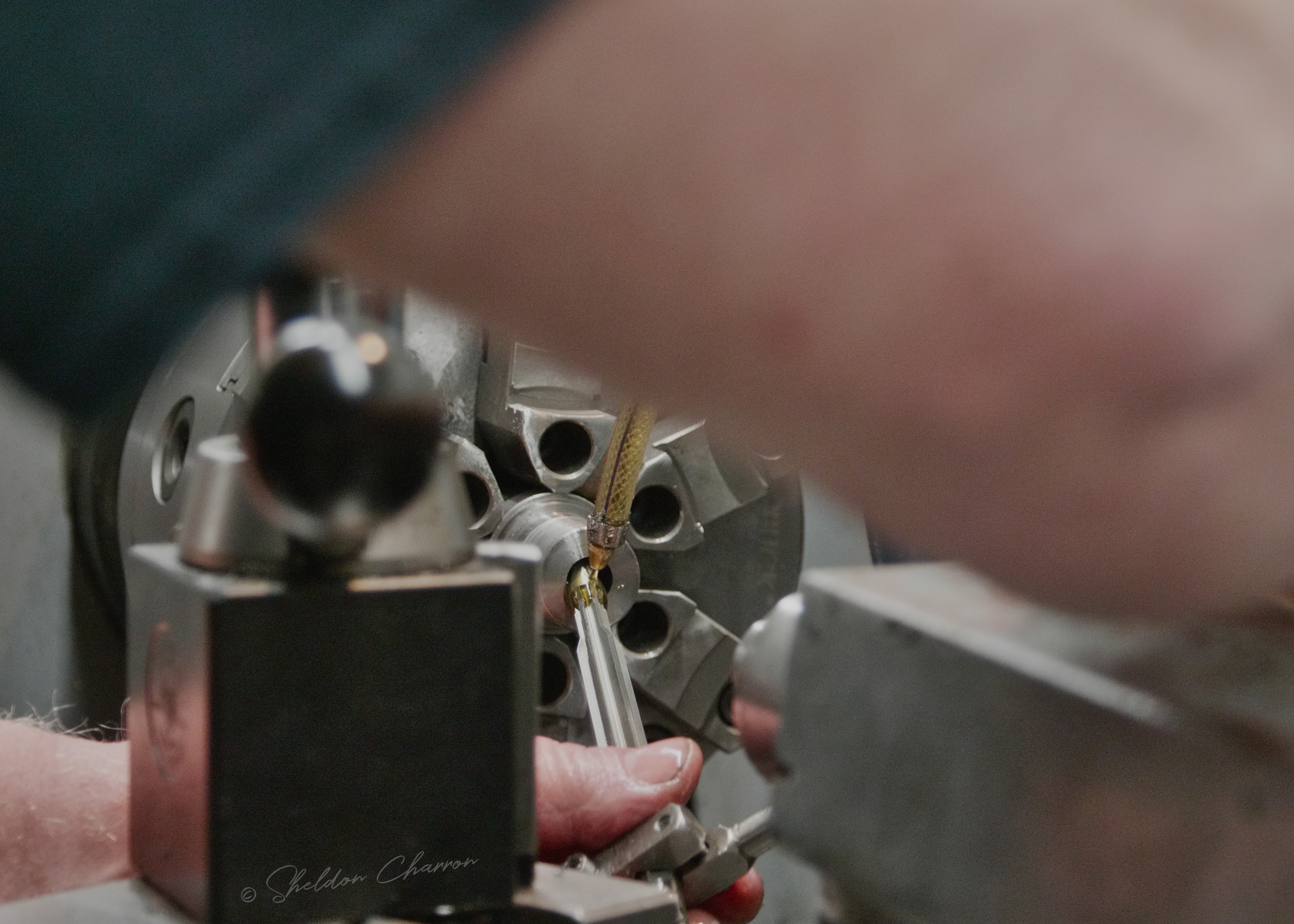
I now have settled on a method that works for me. It is a combination of T. J.’s, Ed’s and Allan’s methods. I use a six jaw adjustable chuck and a spider with four bolts. I run the tailstock of my lathe with a dead center up to within a few inches of the headstock. I push the barrel through the adjustment collar at the back of the headstock, through the headstock and push the chamber end of the barrel up tight against the center in the tailstock. At this point, the jaws of the chuck are not touching the barrel. With brass shims between the 4 bolts in the adjusting collar and the muzzle end of the barrel, I then indicate in the muzzle to 0.0002″ reading on a Deltronic’s pin gage. The dead center on the tailstock allows the barrel to pivot similar to what T. J.’s O-Ring did. (I no longer do this with the dead center, but use the method at the bottom of the page going back to a method similar to T. J.’s O-ring) After the muzzle is indicated in, I then tighten the six jaw chuck . After the chuck is tightened, the barrel is indicated in with the dial indicator reading on a Deltronics pin gage. I use two Interapid dial indicators one at the chamber end and the other at the muzzle end. Both reading on Deltronic’s pin gages initially. The chamber end is indicated in to 0.0005″ with the shortest indicator point for a true .0001″ reading. Then using a Interapid dial indicator with the appropriate length point for the caliber being chambered, I finish indicating the barrel, but this time the dial indicator is reading at the point where the throat of the cartridge will be. Using the long indicator point, the reading has to be as close to zero runout as can be obtained. When the 1.5″ or 2.750″ indicator points are used the dial indicator no longer reads in true 0.0001″. With the 1.5″ indicator point, I try to get the reading to be 1 mark variation or less. With the 2.750″ indicator point, I shoot for 1/2 mark of total movement or less with closer to zero variation the better. When you make your initial reading before adjusting runout the throat is usually not running as true as when the barrel was originally indicated.
At this point, I cut a rough barrel shoulder and barrel tenon with the length of the barrel tenon being same as the measurement from the action face to the bolt face. The diameter of the barrel tenon at this point is 1.075 for a Stolle and 1.005 for a Hall. This is .015″ over finished barrel shank diameter. I then take a 3/8″ drill bit and run it into the chamber end for ¾ to 7/8″. I then open the diameter of this hole with a 25/64″ drill bit. After the barrel is re-indicated, I now take a cut with a small boring bar ( Circle Industries 1/4″ carbide shank with 60 degree .007 radius tin coated inserts) to true up the out of roundness from the drilling operation. I keep boring until I get a diameter approximately .010″ smaller than the diameter of the chambering reamer shoulder. Each pass is set to take off only .001 of metal at a time. After I am through with the boring operation, I take another reading with the dial indicator this time on the bored hole to determine that the bored hole is perfectly concentric. Every time that I do an operation to the barrel, I check it with the dial indicator. If you check out every step, every time, you know that each step is done right before you go to the next step. If you don’t check it, you don’t know if its right or not.
At this time, I run my chambering reamer into the barrel 0.100″ short of finished depth. The chambering reamer is driven by a simple holder on the tailstock that allows the reamer to float slightly and held by hand with the aid of a Sinclair case holder. Holding the wrench by hand it is easy to tell if you try to feed the reamer in too fast. Using reamers with removable pilots, a pilot is selected that is .0002″ under the largest pilot that will fit into the barrel. The pilot is selected by using a special shank that will allow the pilot to be inserted to the finished throat area. I use a high grade cutting oil (Texaco Transultex H) and coat the pilot and reamer and also squirt the oil into the barrel. I will at first go 0.100″ deep with the reamer before I withdraw the reamer. I, then blow chips off the reamer and out the barrel with compressed air. I, now, re-oil the barrel and the reamer and go in another 0.100″ withdraw and repeat the whole process. (I now use a Gre-tan through the barrel flush system instead of blowing the chips down the barrel.) When the chambering reamer shoulder starts cutting into the barrel at the bottom of the bored hole, I quit taking 0.100″ and reduce to 0.050″ deep until I get to 0.100″ short of finished depth.
At this point, I check my nearly finished chamber with the dial indicator. The closer the dial indicator reads to 0.0002″ on the back end of the chamber the better the chambering job is. Run out on the chamber job is greatly enhanced by chambering into the bored hole instead of trying to let the chambering reamer do the whole job of reaming the chamber. It also should help the chambering reamer last longer, too because the chambering reamer is doing less work. I now re-indicate on the back end of the chamber, if necessary. That is if the run out is greater than 0.0002″. I have yet to have a chamber that has run out to as much as 0.0005″ using this method. If the action is in hand, I go ahead and turn the thread shank diameter down to finished diameter(1.057″ for a Stolle, 0.995″ for a Hall). (If the action is in the stock, whether it is a glue-in or I just don’t want to remove the action from the stock. I can either thread between centers and cut the cone on the steady rest or use a thread mike and a cone measuring device and do everything in the headstock.) I will now thread the barrel starting with .005″ to the pass gradually working down to .001″ passes the closer I get to the barrel screwing on to the action. I try to get as tight a thread as I can that I can thread the action on by hand to the shoulder and off again by hand. I will now take a very fine pass across the barrel shoulder to make sure that the shoulder is square to the threads. Harold Broughton told me that when a barrel tightens up against the shoulder the front part of the barrel thread and the rear of the action thread are the only part of the thread that will make contact. There will always be clearance on the back of the thread and it doesn’t make any difference whether this clearance is .0002″ or .001″, its still clearance and won’t affect the way the barrel shoots. That means that a tight thread fit or a loose thread fit won’t have any effect on accuracy. Even though I know that, I still prefer a fairly tight thread fit. A very thin layer of layout blue should be applied to the action face. The action should now be tried to the threads. If everything is right the barrel shoulder should have a full circle of layout blue when the action is removed from the shank.
I now set my compound to ½ degree less angle than the bolt nose. With a Stolle, I set the compound to cut a 29 ½ degree angle. For a Hall, I set the compound to cut a 24 ½ degree angle with the angle being such on the barrel tenon that the farther that you get from the chamber the greater the space will be between the bolt nose and barrel. I gradually start removing the metal for the cone. I check for fit by screwing the action onto the threads with the bolt closed in place in the action. I can then measure the gap between the barrel shoulder and the action face with dial calipers at first and then later with a feeler gauge as the gap decreases. When I get to the point that a 0.010″ feeler gage will fit in the gap. I take one more pass removing 0.015″ metal leaving a gap of 0.005″ between the barrel and bolt nose. The bolt nose should not contact the barrel. It is very important to keep clearance between the bolt nose and the end of the barrel to a minimum. I like to have no more than .010″ clearance between the cone on the barrel and the cone on the bolt. If there is more clearance than that, the case head will not be supported and can result in case head failure upon firing with the case blowing out and releasing gas and shrapnel down the bolt raceway or worse. Keep headspace to a minimum fit on the go gage and bolt clearances to a minimum for the utmost in safety.
We are now fully threaded with proper bolt fit. We are still not completely chambered. The final 0.100″ left to go on full depth of chambering will now be gradually done. The depth of the chamber is measured with a go headspace gage inserted into the chamber and measured with a depth micrometer from the face of the headspace gage to the barrel shoulder. This measurement should measure the same as the measurement from the action face to the bolt face when the chamber is finished. When the chamber gets to the point that it still has approximately 0.020″ left to go using the depth micrometer, I change to what I believe is a more accurate method of achieving final headspace. That is to screw the action with bolt in place onto the barrel with the go headspace gage in place. The gap between the barrel shoulder and receiver face can now be measured with a feeler gage just as it was when we fit the coned bolt. Go slow in finishing the chamber as it is a lot easier to do if you don’t go too deep. The bolt should just close on the go gage with the action screwed down against the barrel shoulder.
After the front end work is done, I now turn the barrel around in the headstock , set the compound to cut 11 degrees and crown the muzzle. I have crowned barrels using a good sharp tool and cutting a 60 degree center, taking a ball bearing and working from 320 grit down to 600 grit sandpaper or using a ball and lapping compound. I can’t tell that one works particularly better than the other. But, with the ball it is possible to push metal into the bore resulting in a fine bur completely around the muzzle. You can tell by taking a q-tip and running it around the crown. If there is a burr, it will catch on the q-tip. The crown has to be burr free.
After the barrel is chambered, threaded and crowned, I will take thread mike readings on the barrel, cone length readings with a special dial indicating fixture and record depth mike readings for headspace readings. Also, I have a fixture made for indexing the caliber engraving on the barrel. All of these are recorded for subsequent barrels on the same action without having to have the action in hand in the shop. (This is done on the custom actions only. There is too much variation in production actions.)
So, how well does this method work? Well, the first barrel that I chambered like this was a Broughton 9-groove .22 Waldog . I finished the barrel job on Thursday. Shot it that Saturday in a registered match in Oklahoma City. I was second at 100, won the 200 and finished by winning the grand. Then the next month won the grand again. The competition at the Okie Shooters Range is tough. Some of the hottest shooters in the United States shoot Oklahoma City. The method outlined above has been slightly changed and updated over the years since the Oklahoma City matches, but is basically still the same procedure and step as used then. Steps that have been changed since then are that I used to drive the reamer with a dead center. I no longer do that. The simple reamer holder that I use is pictured below. It works much better than any manufactured floating reamer holder that I have used.
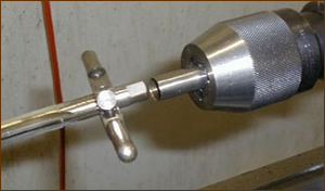
Above – The Simple Reamer Holder. The holder is bored .020″ oversize of the reamer shank.
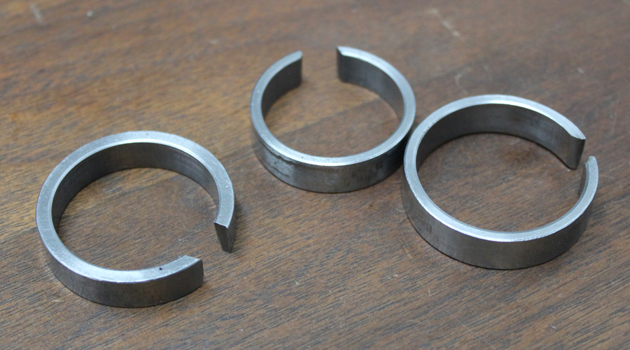
Above – Update 2019. This is the collar that I now use to go around the outside of the barrel on the chamber end. With the collar around the barrel and the collar held tight in the adjust true 3 or 6 jaw chuck, you can take the muzzle end of the barrel and move it anywhere you want in the spider end of the headstock and it will stay where you move it. This indicates that the barrel isn’t being bent. The collar is a 1/4″wide ring that is 1.350″ in diameter bored out to slip over the barrel with a few thousandths clearance. The slot on the ring lets the ring tighten down against the barrel when the chuck jaws are tightened. When the chuck jaws are tightened down, they only bear against the ring. The chuck jaws do not bear directly against the barrel itself. If the ring is not used and the jaws are tightened directly against the barrel, you can push the muzzle end of the barrel, let go and the barrel will return to the original location in the spider. This indicates that if you adjust the barrel in the spider that you are actually bending the barrel. The collar solves that problem.
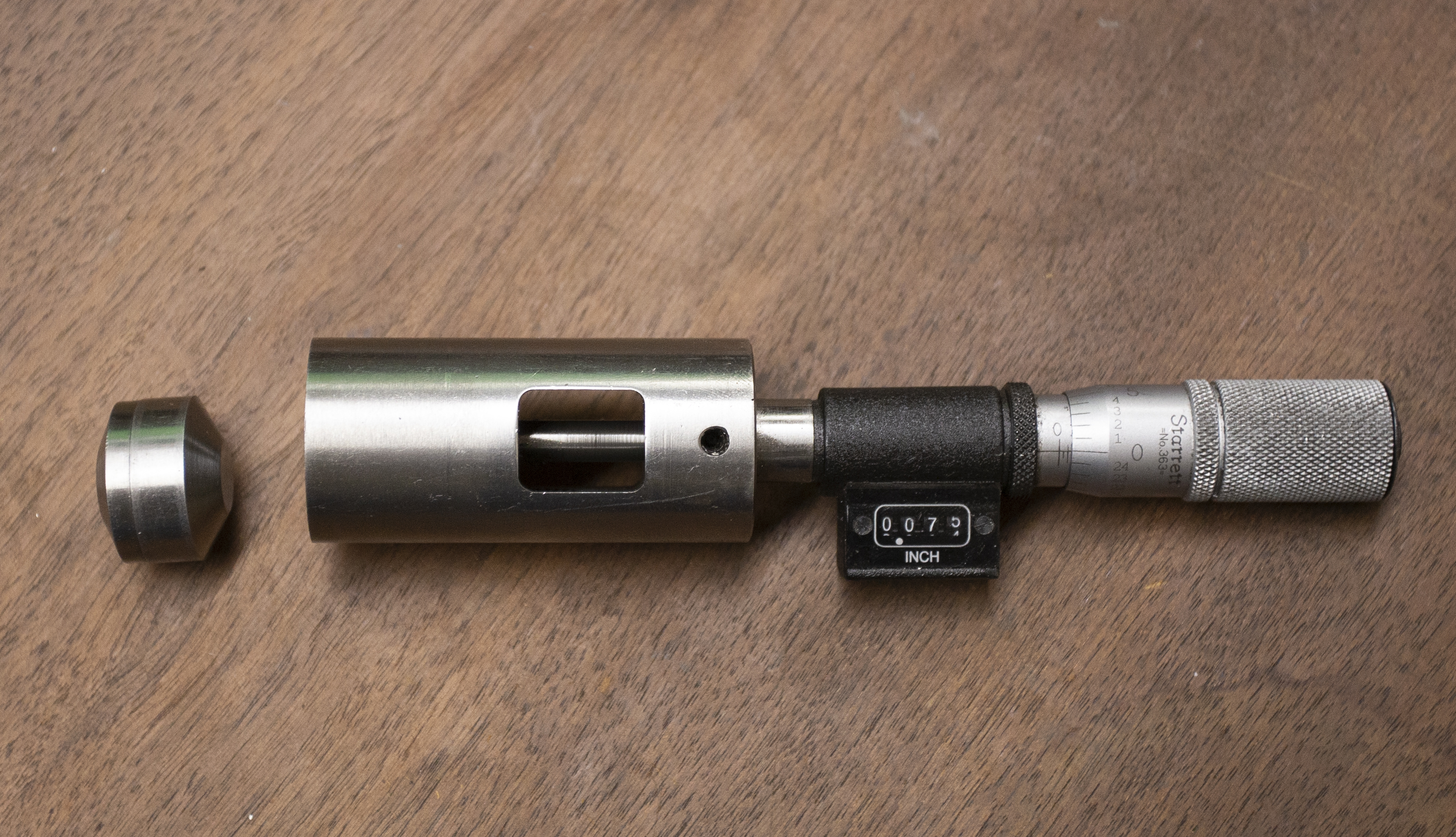
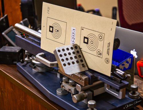
Above – The tool that I use for measuring the cone on previous barrels. The coned piece in front of the tool is a reversible 25 degree or 30 degree cone for use in measuring the depth that the coned breech is cut on the barrel. The 25 degree side is used for measuring Bat actions and the 30 degree for most others. I also use the measuring tool for a direct reading off a headspace gage. The micrometer head is set to 0.000 using a 1″ ball and a surface plate. That way the head directly corresponds to the depth micrometer reading from the receiver face to the bolt face inside the action.
Below – A photo that I took of a Bald Eagle floating reamer holder that a customer sent me to use with his reamer setup. Unfortunately, I couldn’t use it as the reamer holder has a #2 Morse taper and my Kent lathe uses a # 3 Morse taper. The Bald Eagle reamer holder is a little more polished version of the tube that I use to float my reamers.

Above – The two set screws in the front of the black tube tighten down on the reamer shank and the black tube floats on the rounded pilot turned on the end of the Morse Taper shank. The ball end of the pilot pushes against a steel insert inside the aluminum tube. The tip of the ball nose has one point contact with the hardened insert. There is about .035″ clearance on the diameter between the ball nose and the inside of the tube. With the floating reamer holder that I use, the Sinclair case holder tightens on the reamer shank and then the reamer shank floats inside the tube that pushes the reamer forward as it cuts the chamber.
Tools used are Isccar turning holder SWAPR-1414-06 with WPEX 060402R08 carbide inserts for turning to a right angle. The boring bar used is a Circle Industries F series 1/4″ solid carbide shank with 60 degree carbide inserts with .007″ radius on the tip of the insert. I’ve tried the Circle 1/4″ bars with trigon inserts and they don’t work nearly as well as the 60 degree inserts for barrel work. Unfortunately, Circle Industries has sold out. I’m now using Hertel or Kennametal boring bars with the triangle inserts.